The chide in the helicopter world is that excessive vibration is the unsolvable path to early destruction. Truth is, piston airplanes are a close second, and yes, the sit-up-straight paranoia-inducing vibration you feel in the floorboards while over large bodies of water is real.
Getting an airplane to fly smoothly enough to keep passengers satisfied and components healthy goes beyond a well-tuned engine and balanced props, although that’s often the starting point.
In the end, troubleshooting and fixing abnormal airframe vibration is a tedious multi-step process best left to the pros, but here are some basic things to consider before bringing the aircraft to the shop.
Is That Normal?
Face it, some airframes inherently have more perceived vibration, simply by nature of their parts. Hang a fat wide-chord or even a long two-blade paddle prop on some airplanes and you’ll likely feel a distinct rumble in the climb.
But aero engineers also rightfully place vibration in two categories: normal and abnormal. Jets aren’t immune to either. No matter the engine, it has to sit on healthy engine mounts and be mated with a compatible prop, something the OEMs usually get right when mating propellers and engines for the aircraft’s final type certificate.
If you’re changing the original engine/propeller combination (say from a standard two-blade to a three-blade model), understand that you might be happy with the increased performance, but not with the induced vibration. We know of a particular Piper Cherokee Six 300 that from a vibration standpoint wanted no part of an STC’d three-blade prop upgrade, and its owners ultimately took it off when the shop just couldn’t make it smooth.
As you would expect, years of wear and tear, plus neglected maintenance, is a recipe for abnormal vibration. There are good reasons to minimize vibration, and it’s not just about comfort. Avionics, while built to sustain reasonable amounts of airframe vibration, do fail prematurely in vibey airframes, especially spinning gyroscopes.
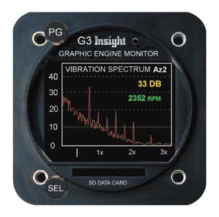
On a side note, the popular vintage King KG102A remote heading gyro that’s part of the KCS55A HSI system sits on a mount housing equipped with four shock mounts, which proves how critical vibration is to this component (an overhaul nears $2000). The health of the shock mounts can tell a story of how much vibration is present in the airframe, and how long a freshly overhauled gyro might really last.
Engine Isolators
Although we’re primarily concerned with airframe vibration for this article, it’s worth a few words on engine mounts, or engine isolators, as they’re more appropriately called. We covered them in detail in the January 2015 Aviation Consumer. These elastomer donut-like components that live between the airframe and the engine serve the important purpose of dampening the rigid airframe from the hammering vibration of the engine and propeller. Engine vibes can certainly do damage, including cracking major structural components, loosening rivets, fatiguing metal and damaging instruments, to name a few issues. Steve Gruenberg, a professional vibration analyst, told us to “Think of airframe vibration as multiple impacts-as in taking a hammer to the structure.”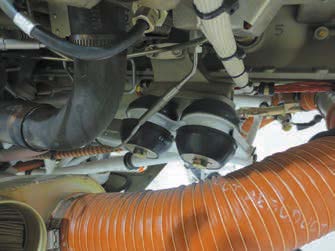
Unfortunately, engine isolators are often overlooked when they beg to be replaced, even during engine swaps or when the engine is overhauled-which is perhaps the most opportune time to replace them.
Most engine mounting systems use four isolators, although some aircraft use six. The Continental engine mounting system supports the engine from below-think of a person holding a beach ball. Lycoming engines are cantilevered out from the firewall, so the top isolators are loaded in tension, the bottom in compression.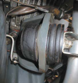
While some isolators can last beyond engine TBO, nearly every tech we spoke with said it’s more realistic to think of them as good for 10 to 12 years. They should be inspected for condition regularly. They are all made of a compound based on natural rubber, which means that they will eventually solidify and deteriorate. Plus heat, oil and avgas are the enemies.
As the isolators wear out, the engine will sag on the mounts and vibration will get worse. As the engine sags it can and will come into contact with the cowling and items within. Worst case is the engine ring gear cuts into the lower cowling and starts chafing wires and fuel lines. Ugly.
Replacing a set of isolators takes anywhere from three to 12 hours. It involves loosening mounting bolts and hoisting the engine a few inches away from the mount, and then loosening or moving cables and lines as needed. Once there is adequate clearance, the bolts can be withdrawn and the replacement isolators installed. But you have to do it right, otherwise you can create vibration like we once witnessed on a Cessna P210.
After throwing a lot of money at troubleshooting by looking for a shuddering problem in the wrong places, the mechanics found the problem was a shanked-out isolator bolt. Closer inspection found that the left front isolator was tight in the attachment threads, but not against the structural leg. That play in the mount pack created a heavy, dull vibration felt mostly in a climb configuration as the engine rocked around.
Last, hard and sagging shock mounts will do little if any good at isolating the engine from the airframe. Instead, they’ll transmit the vibration from one hard point to another.
Control Flutter and Other Culprits
Let’s get back into the airframe for other sources of vibration. The vibration created by worn control surface hinge points and out-of-balance control surfaces can be subtle in its impact but increasingly destructive in nature. Balancing controls whenever repair or painting of a surface is accomplished is not only prudent, it’s a requirement that doesn’t always happen.
Even a slight imbalance of a control can cause a high-frequency oscillation that is dampened by the control cables but can still be felt in the control wheel. Manufacturers are stringent when it comes to trim tab free play. The main concern is for control surface flutter, which can lead to hinge-point failure and loss of control, but the rattling going on with several loose tabs can be unnerving. While difficult to feel, a slight increase in control wheel or rudder pedal “buzz” can be found by increasing the aircraft speed toward Vne.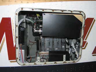
Don’t wait to make the necessary repairs. Vibration caused by loose trim tabs is not only annoying, it’s downright dangerous. The real fix is replacing all associated hinge points, rod ends, bushings and bolts, as needed.
Still, control flutter and engine/prop issues aren’t always the cause of vibration. Aircraft sometimes develop vibration issues associated with rig or a broken fairing, a bent or cracked landing gear door or even a cracked wingtip. Just forcing air out of the way in an effort to stay aloft also creates some vibratory noise. We recently learned that even gliders have some degree of vibration, particularly at certain speeds.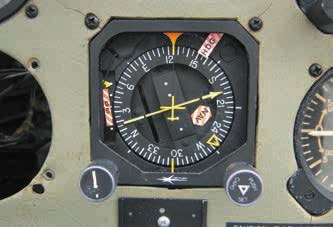
It’s even more frustrating when the engine is running smoothly and there are no airframe vibes on the ground, but it all changes for the worse when airborne, where many factors come into play.
Impact air against the airplane, flexing of the fuselage and pressure-box buildup within the cowling can reposition inspection covers, baffling, cowl flaps and doors. Anything and everything attached to the airplane can cause some form of vibration or be caused to vibrate in response to tension-release input.
Propeller Balancing
Probably the first thing that comes to mind when considering a vibration problem is the thing that has the most potential to vibrate: the prop. All propeller manufacturers establish balance criteria for their props. Across the board, regardless of make and model, the propeller is considered in balance when it can rest evenly on a knife edge beam without dropping a blade in either direction.
Typical tolerances for static balance are plus or minus one weight. The gram equivalent will vary depending on the propeller, and the weight slugs can vary in size, but getting it on the money is the goal.
Aside from outright balance, propellers are checked for blade track and blade angle (including relative to each other). All props will have slightly different specifications. Your prop shop should be consulted for the particulars on your aircraft. In addition, most propellers can be positioned on the crankshaft in one of two ways.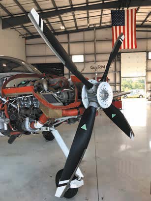
Typically, the number-one blade on the prop is placed at the top center mark on the crankshaft flange. Three-blade propellers are often installed with the number-one blade up or down, depending on balance requirements and the aesthetics of having both props positioned the same way on shutdown.
One distinct causal issue is where the prop blades are slightly out of specification with respect to each other. The prop needs careful spec checks when there are thorny vibration issues.
As was the case with our previously mentioned Cherokee Six example, ironically, switching an old airframe from a two- to three-blade prop can sometimes lead to endless vibration issues that can only be resolved by returning to the original two-blade prop. Again, use the original type certificate data sheet as reference for selecting an upgraded propeller. While you’re at it, ask others with like-model aircraft who have made the switch if they encountered vibration after the upgrade. It’s common sense, but don’t install a propeller that’s not approved for your particular model aircraft. We’ve witnessed it and the poor results that followed.
Regardless of the make and model, current wisdom dictates the use of a dynamic propeller-balancing machine in order to trace and hopefully eliminate prop vibration. It may be the very thing needed for the airplane that rattles through the air, but it should be the last thing accomplished in the vibration troubleshooting process, which also includes a detailed propeller specification check.
Worth mentioning is it does no good to dynamically balance the propeller if you have a partially plugged injector or if your exhaust stack is hitting the bottom cowling. In these circumstances, prop balancing may only help mask a potentially serious issue.
What’s That Rattling Sound?
Airframe vibration can be very difficult to pin down because the smallest of vibration sources can be amplified by the “drum effect” of wing and tail cone recesses. Of particular concern are cowl flaps, gear doors, wing and tail fairings and cabin doors and windows.
Ever notice that speed increases make rattles and vibration worse? Generally speaking, an increase in aircraft speed will bring about an increase in the pitch and frequency of the vibration, although it does not always happen like that. Sometimes, deck angle will impact an ill-fitting nose gear door in the climb, causing a rumble as air loads buffet the nose gear wheel well, as was the case with a particular Piper Saratoga we used to fly.
Piper main gear doors are particularly problematic because of the poor fit caused by warping of the fiberglass door material. Adjusting the rod end to pull the door closer only aggravates the problem by cinching up the one side while the other sags with the strain.
Cowl flaps are a common vibration source because of the wear occurring in the hinge-pin area. When the flap is pushed open, the air load holds the door in one position, regardless of the amount of hinge-pin wear. But when the cowl flap door is closed, the control cable pulls upward on the rear of the door, allowing the forward hinge and hinge pin to float. This play then allows the hinge pin and cowl flap to vibrate, causing even more pin wear.
Externally mounted components can wreak havoc on your smooth-running engine as well. Baffling that rubs inside the cowling, exhaust stacks that hit the lower cowl openings, crossover intake pipes that interfere with nose bowl structures and loose accessory mountings will produce a variety of noises and shudders. Even fluttering antennas add to overall vibration. We’ve seen antenna flutter severe enough to rip the thick skin of a Bonanza.
Good installers reference the procedures outlined in the antenna installation guide, along with guidance written in the FAA’s AC 43.13-2B. We’ve seen plenty of installations done without the proper skin doublers or reinforcement. Need a skin repair? Get ready to write a fat check.
You wouldn’t think so, but alternators and generators contribute to high-frequency vibration when the internal rotors and bearings come out of balance.
It’s Getting Old
It’s often a tough life for aircraft and things just don’t stay factory-tight forever. If you’ve done major avionics upgrades there’s a good chance the interior (including trim pieces, vents, headliner and panel molding) was removed. This often means cabin rattles bad enough to trigger vibration and noise.
And remember that dark, stormy night on the ramp when the passenger flung the door open to the wind? It might mean the door is out of rigging, if not damaged.
Sure, cabin doors and windows are notorious for causing wind noise and water leakage, but the burble created by a poor fit between the door and the frame can cause a “drumming” against the fuselage and vibration in the thin windows aft of the door.
Occasionally, no amount of rigging will get the door to sit flush in its frame. Years of flexing, combined with the warping that occurs every time the wind grabs the partially open door, will make cabin doors and windows difficult to fit.
Pay close attention to the instrument panel for vibration. Many so-called floating panels attach to the structure with shock mounts to dampen the vibration on the instruments-especially spinning gyros.
Wrap It Up
Like new cars, new airplanes are generally vibration-free and keeping them tight means keeping up with maintenance. That means spending money on rigging, prop balancing, engine mounts and even an interior upgrade. New interior hardware, carpeting and modern seating can work wonders at taming the cabin dwelling, as can sound-deadening material.
We recall a service kit once offered by Cessna that included 1/4-inch thick, sticky-back foam sheets on flat sheet metal surfaces between formers and bulkheads. Made of dense foam covered by a layer of thin foil sheeting, the sound-deadening material was cut to fit and glued down on forward and aft bulkheads, belly pans and on fuselage skins.
This material worked we’ll to keep the aluminum skins from vibrating in response to air loads and exhaust burble. Far as we can tell, these kits are no longer available, but there are plenty of aftermarket sound-deadening kits and mods to try. We’ll look at them and interior upgrades in an upcoming market scan.