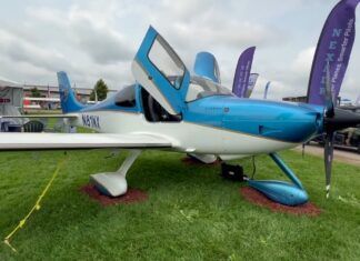
Step up to a complex airplane and eventually you’ll deal with maintaining the constant-speed propeller governor. While instructors rarely teach more than the things to look for on the preflight walk-around (oil slung on the prop blades, for one), not enough emphasis is placed on the importance of keeping the governor healthy, while also recognizing the signs of pending failure. Here’s a primer.
PROP GOVERNORS 101
The prop governor is nothing more than an externally mounted oil pump that selectively “leaks” oil pressure from anywhere between 50 to 280 PSI as needed to the prop hub. There, it’s converted to mechanical piston motion to effect prop blade pitch changes.
These things have been around since the late 1800s, when Amos Woodward patented the first governor made for water wheels. Of course, some engines have always had so-called solid crankshafts, and they can’t be used with conventional hydraulic propellers because there’s no way to route the oil out to the prop. Eventually, the governed constant-speed (as opposed to controllable pitch) prop saw emergence in general aviation airplanes in the 1950s. Still, the Woodward governor (among others, including Hartzell, MT, Hamilton Standard and McCauley) is common today and found on a variety of Lycoming and Continental engines, boosting engine oil pressure to move the propeller.
Think of the governor as an RPM-sensing high-pressure system, responding to RPM changes by lowering or increasing oil pressure so that the change in oil volume in the governor’s hydraulic cylinder changes the propeller blade angle. It also maintains the prop’s specific RPM, with the pilot manually adjusting the prop control (unless it’s a Cirrus where it’s done automatically).In normally aspirated SR models, the throttle lever is connected to a mechanical cam and via a cable connected to the prop governor, the system moves the prop control as the throttle is moved fore and aft.
Governors were game changers from the days of ground-adjustable and two-position props. A ground-adjustable model requires a mechanic to change the blade angles manually—think fixed-pitch prop that you could adjust only on the ground. The two-position prop was somewhat better in that it allowed the pilot to choose one of two preset blade angles: low pitch (high thrust at low airspeed) and high pitch (efficient cruise) while in flight.
It got even better when Beech introduced the electric prop, including the Beech Model 215 on the Bonanzas. This enabled the pilot to choose the most efficient engine RPM and throttle setting rather than just the most efficient engine RPM. All this meant shorter takeoff performance, better climb rates and better cruise speeds. But, the rub was that the selected prop angle stayed the same until someone changed it. It was high workload for the pilot, having to jockey the throttle or blade angle to keep the engine and prop from going out of their RPM limits with altitude or airspeed changes.
But what if the propeller blade angles were controlled by a governor that automatically keeps engine RPM at a constant, pilot-selected value? Bring on the constant-speed propeller, which enables the engine to put out full RPM and maximum torque for takeoff and situations that require maximum power, while allowing high torque during cruise flight without overspeeding the engine. Better yet, the governor takes care of monitoring. Beech was among the first to offer this luxury on its H-model Bonanza somewhere around 1957.
SIMPLE DESIGN – MOSTLY
The governor is obviously the most complicated portion of constant-speed propellers. In reality, the most common general aviation constant-speed prop propeller is nothing more than a single-acting, spring-balanced hydraulic cylinder with piston actuating rod(s) attached to offset pins in the pivoting blade shanks. Oil pressure acts only one way in this design. A combination of centrifugal force and counterweights and/or springs acts to move the blades in the other direction when the oil pressure is reduced via the governor.
This allows the blade angle to be selected depending on the amount of hydraulic pressure applied to the inside of the cylinder/piston assembly (sometimes called the prop dome). This pressure comes from the governor itself, which has its own internal oil pump to multiply nominal engine oil pressure up to 280 PSI, depending on the governor make and model.
Got clean engine oil? It’s important to governor health because there is continuous circulation of normal engine oil in the basic governor design, and there is no separate hydraulic fluid.
You’ll hear the words “increase” and “decrease” used a lot in the world of governors. Although there are a number of different designs in hydraulic constant-speed propellers, there are only two methods used to change blade angle: pressure to increase blade angle and the pressure to decrease the angle. We won’t touch on the double-acting hydraulic governors, primarily used on large radial engines and turboprops.
This is somewhat confusing to a lot of pilots because they’re used to speaking in terms of propeller RPM, but on the shop floor we talk in terms of propeller blade angles. This language barrier between the pilot and mechanic can send the troubleshooting in the wrong direction, so get it right. At a given torque, the blade angle has the reverse effect on RPM—a decrease in blade angle increases RPM and vice-versa. If there’s any question, take a skilled propeller tech for a short flight to demonstrate the issue you’re seeing.
SINGLES, TWINS AND FEATHERING
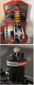
Oil pressure to increase prop angle via the governor is used on virtually all single-engine piston aircraft. The prop governor routes oil pressure to the propeller dome, the piston moves back and the blade angle increases, which loads up the engine and decreases engine RPM. The spring behind the piston in the dome and the blade’s centrifugal twisting moment (CTM), or the tendency of the center of mass in the blade to take the blade to fine pitch or low angles, provides a counteracting or balancing force for the oil pressure in front of the piston. This balancing act provide a fine-tuning ability that will allow a healthy governor to maintain the engine speed to a nominal 5 RPM, except maybe on some of the older props with no spring.
Oil pressure to decrease prop angle via the governor is used on most twin-engine aircraft that have feathering propellers. An increase of oil pressure in the cavity behind (on Hartzells) or ahead of (on McCauleys) the piston causes the blade angle to decrease. The counteracting forces in this prop are usually the blade counterweights (to overpower natural blade CTM), and powerful springs on the piston backside (on a McCauley).
In the case of Hartzell, a prop dome filled with compressed nitrogen along with a spring on the piston front side is used (if the applicable service bulletin is complied with). Using these combined forces, a continued loss of oil pressure in the dome allows the propeller to go to full feather. A separate “accumulator” is used on some Hartzell and McCauley props and is designed to speed up the unfeathering process. This is done by storing a quantity of oil under pressure, typically in a spherical container with a rubber diaphragm inside that separates the two sides. One side is charged with nitrogen and the other is filled with oil. When the prop is feathered, the accumulator valve closes—trapping oil that’s under pressure. At the right time, the valves open for more push to get the propeller out of feather. Transitioning to a new aircraft with feathering props? Take extra time to understand the system in both normal and failure modes.
WHICH GOVERNOR?
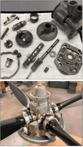
They are matched to a given propeller, and the model depends on the aircraft’s type certificate, usually, or the STC for a prop replacement from stock. Generally, typical GA airplanes use Hartzell, McCauley and also Woodward governors—which are compatible with both McCauley and Hartzell props. But these are basically designed the same, and there are three major assemblies.
There is the governor assembly, the pilot valve assembly and the pump assembly. The governor assembly includes the speeder spring, the speeder’s worm screw and the flyweights.
The driveshaft and pilot spool make up the pilot valve assembly. The pump assembly is comprised of the drive and idler pump gears and the pressure relief valve.
It’s important to understand how oil is transferred from the governor to the propeller. The two most common are the separate transfer collar and oil transfer via a special cavity in the front main bearing. The Continental O-, IO-, TSIO-520 and 470 series engines (with phase two or later cases) use a separate transfer collar. Continental 470/520 series engines with phase one and earlier cases, Continental 360 series and direct-drive Lycoming engines use a separate cavity in the front main bearing.
Continental phase one and two cases are “light” cases, whereas phase three cases are known as “heavy” cases with distinctive bumps along the spine of the case—pretty much the most common now.
A third method—using a close-tolerance tube from the case to the center of the output shaft—is used by the geared GTSIO-520 series Continental engine.
HOW IT WORKS
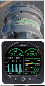
The governor uses a balance of flyweights and a spring to sense changes in RPM. The pilot valve is the component that does all the porting of oil to control the prop blade position. The single-engine governor’s pilot valve ports pressure to the prop when pulled up by the flyweights and then dumps oil from the prop when pushed down. Oil—clean oil—is a good thing, and you can see why sludge buildup won’t be good.
That’s because precise oil metering is done by a plunger type valve inside the hollow drive shaft of the governor, which, by moving up or down the assembly, covers or uncovers oil channels leading to outlet ports of the governor. It goes on to the prop dome by one of three methods.
Centrifugal flyweight action, counterbalanced by an opposing speeder spring, maintains the pilot valve in any given position to maintain RPM. This position is selected by the pilot via a vernier cockpit cable connected to the governor.
On twins, the feathering governor works the opposite; when pulled up by the flyweights or feather rod, it dumps oil out of the prop, and when pushed down it ports oil to the prop.
From an operational standpoint, you’ll be concerned with three modes or conditions of operation: underspeed, overspeed and on-speed. An underspeed condition results when the flyweights are pushed in by the speeder spring and position the pilot valve to decrease the blade angle (dump pressure for singles and increase pressure for twins) and speed up the engine RPM. This increase in RPM continues until the flyweights reach the on-speed position.
An overspeed condition is where the flyweights overcome the speeder spring compression and position the pilot valve to increase blade angle. This causes the pilot valve to port oil (pressure on the single and dump pressure on the twin) to increase blade angle and bring the engine RPM down to again position the pilot valve to the on-speed condition.
CARE, FEEDING, FAILURES
Unanimously, propeller techs we talked with said the best thing you can do to prolong the governor life is keep clean oil in the engine. You should also look for subtle (and sometimes not so subtle) symptoms including the system’s inability to hold a certain RPM, the prop surging or seeking an RPM and in twins, the propeller occasionally going into uncommanded feather.
Perhaps the most common symptom is reduced control over prop RPM (too high on singles, and too low on twins). The problem may be a leak at the case-to-crank transfer point, low oil pressure or a leaky pilot valve in the governor.
Of course, a major concern is corrosion setting in—another reason for frequent oil changes especially if the aircraft sits for long periods. Like the engine, oil contaminated with moisture will eventually corrode the aluminum parts in the propeller, causing piston seal leakage. Then there is oil contamination from debris, although the governor intake screens can catch smaller particles that can cause scoring or galling in the governor and its transfer system. Remember, a healthy governor can reduce the risk of engine oil contamination and ultimate engine failure.
We’re told that one symptom of a clogged governor oil screen (or sludge in the oil transfer lines) is the delay in prop cycling, which can easily be spotted during a thorough runup. When cycling a prop at the recommended power setting, there shouldn’t be any more than a couple seconds’ delay. During winter ops in cold temperatures, keep a close eye on oil pressure and oil temperature. Because a constant-speed prop needs the oil to be thin enough to pump through narrow passages, a takeoff with thick, cold oil might result in a poorly governed prop and even an overspeed.
Propellers and governors have recommended overhaul intervals based on flight hours and calendar time. Depending on the model, the interval and can be 1000 to 2000 hours, but shops tell us that the calendar limit (typically five years) is often ignored by owners who fly fewer than 100 hours per year. That results in some propellers (with 2000-hour intervals) and governors going 20-plus years without being serviced.
Pick a seasoned and thorough shop to care for the propeller and the governor. Done right, a governor should be completely disassembled to inspect and clean the internal components. During non-destructive testing, techs are looking closely for signs of corrosion and pitting. Moreover, each manufacturer specifies a list of parts that must be replaced at every overhaul. This includes gaskets, seals and O-rings—usually included in an overhaul kit. There’s also the mandatory compliance of service bulletins and ADs. It’s not uncommon for shops to perform a magnaflux inspection on components that aren’t replaced, in order to spot hairline fatigue cracks and other flaws.
Prices for overhaul and overhauled exchanges are all over the board and vary by model, but typically run around $1700 for common Hartzell, McCauley and Woodward applications. Freight charges (some shops will pick up and deliver) and removal and installation can add significantly to the bottom line.


