Alternator Tech 101: Troubleshooting Basics

Arming yourself with a bit of tech savvy can help you recognize the early signs of charging system failure. Some basic hands-on can narrow down common problems.

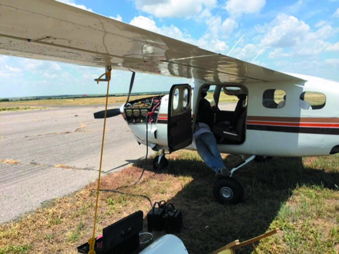
The charging system on the typical GA aircraft isn’t exactly what we would call ultra-modern. But it’s complex enough that an unexpected failure can leave you stuck far from home, while failures in flight can be full-up emergencies.

Even if you don’t have the credentials and knowledge to tackle repairs on your own, there is some basic troubleshooting you can do to catch a failure early, while potentially saving some shop labor so your mechanic doesn’t have to start from scratch. Here’s a primer.

How’s That Battery?

Once the battery does its job starting the engine, a healthy alternator keeps it charged, while powering the electrical system even at low engine RPM. When the alternator isn’t doing its job, there’s often a clue: You change batteries a lot. A charging system that keeps a constant (non-fluctuating) voltage across the battery usually makes for long battery life. Longer yet if you keep the battery on a charging tender. But alternator design for piston engines has changed little over the years, and voltage regulator issues remain common.

The regulator system senses the alternator voltage at a predetermined set point and adjusts the field current to keep the output voltage at the desired level. Digital engine monitors are a good way to keep an eye on fluctuations in regulated voltage, but understand that you’re looking at bus voltage, which is further downstream. What’s normal regulated voltage? What’s listed in the service manual rules, but 13.75 to 14.5 volts on 14-volt systems and 27.5 to 28.5 volts on 24/28-volt systems is the desired range. In a practical sense, know where the voltage sits for your system and monitor it closely at all power settings and under different electrical loads. One thing you might do—that many do not—is precisely set the limit warning in the engine monitor so it will get your attention during brief voltage excursions. If you’re seeing occasional fluctuations that don’t feel right, something likely isn’t right.

Kelly Alternator

And yes, there are sensors in the system that might fail, including the output sensor, or alternator-out sensor. It’s usually wired to the AUX terminal lug and triggers a warning light when voltage from the positive diode plate has dropped to a level that prevents the alternator from producing current.

The regulator senses the alternator-out condition by determining whether current is going to, or coming from, the battery. Read the aircraft POH carefully to understand what the panel annunciators are telling you. In general, when current flows from the battery, the regulator throws the alternator-out light. In many Cessna singles, this light is labeled “High/Low Volt.” In Pipers, it’s the “ALT” indicator.

There’s also the overvoltage unit generally connected in series, via the power wire to the regulator, between the alternator switch and the regulator. It senses voltage, and when it senses it’s too high, it disconnects the power from the regulator. With it out of the picture, the field has no source of current and the alternator stops producing power. You should know the procedures for bringing the overvoltage unit back online. Typically, cycling the alternator switch off and then back on resets it.

There’s also low-voltage sensing, and you’ll see the annunciator when the system voltage drops to within one-half of a volt above the battery voltage. A common culprit here might be the battery and not the charging system at all. In many cases, a low voltage situation can be detected in the audio system. You might here a strange tone in the cabin speaker, and when the voltage drops real low, the audio might be unusable.

voltage annunciator

It’s important to remember that the low-voltage function, unlike the high-voltage function, does not shut down the field current. This is because the alternator may just be in an intermittent overload or may still be able to provide enough current to run essentials. Many older singles don’t even have a voltage sensor.

Eating Regulators?

We’ve seen the cat and mouse game of replacing multiple regulators, when in fact a deeper problem is ruining them. If the alternator field is shorted or the brush slip rings are badly damaged or built up with carbon and oil, the alternator could well be the cause of the regulator failure. It could also be the ground fault protector (in the newer units only) tripping the regulator offline.

You’ll need a VOM (volt/ohm meter) to do a quick resistance check at the field terminal of the alternator, with the field wire disconnected. This is to see if the field is grounding inside the alternator or to see if the brushes aren’t touching the slip rings.

The VOM will jump around somewhat while turning the alternator rotor during this check but should never fall below the ohm value of a good rotor. This is 4 to 6 ohms for 12-volt alternators and 10 to 12 ohms for 24-volt alternators. The resistance should also not be consistently high. If it is, and there is no fluctuation when the rotor is turned, then the brushes are in poor contact with the slip rings. Getting to the brushes may be easier than you think. On some alternators, it’s a simple matter of removing the brush pack. A very fine, clean Scotch-Brite pad can be used to clean the slip rings by pulling the prop through (check mags and battery off) with at least one plug out of each cylinder.

Hold the Scotch-Brite pad in place on the slip rings and spin the prop through a few revolutions. Don’t rub back and forth, as this will brighten up the slip rings and not put any cross scratches on them.

With luck, this can often cure a problem where the first inclination is to replace the regulator.

If there’s voltage at the field terminal and the field continuity/resistance check appears good, then you need to find out if the alternator is putting out voltage. If so, is it being shut down by the overvolt unit?

Confirm continuity for the positive battery cable to the bus and connect the VOM to the bus to read bus voltage. Start the engine. With the engine at about 650 RPM, put a fairly heavy load on the electrical system: landing and taxi lights, interior lights, fuel pump(s), beacons and strobes. Switch on the alternator. On most systems, 650 RPM is too low for the alternator to bring the system above battery voltage under load, and the voltage will be below the normal system (not battery) voltage.

Slowly bring the engine RPM up while watching the VOM. The voltage should increase with RPM until it reaches normal system voltage (as sensed by the regulator). On properly operating systems, it will stay there even with an engine RPM increase.

If the voltage keeps rising, provided the overvolt unit is working properly, the bus voltage will suddenly drop to battery voltage with a corresponding alternator-out indication. This means the overvolt box did its duty and shut off power to the regulator. The problem here is going to be in the regulator, likely a short. Worth mentioning is there are generally three basic failure modes of the regulator circuit: an open condition in the field power transistor, a short in the same or a partial short.

An open will give no alternator output, while a short will result in an overvoltage state. Partially damaged field circuits will cause the regulator to go over voltage with a higher engine speed and little or no load. It can also be indicated by difficulty in setting a consistent system voltage.This type of failure is not common but will cause a lot of hair pulling if you’re not aware that it may occur.

When one stator phase or an alternator diode fails, the others are usually not far behind. The regulator tries to bring the voltage up and keep the load the same, as it should.

However, this added load on the remaining phases or diodes will heat them up past their maximum allowable temperature and cause further failures, especially in high current demand situations. A bad diode or stator phase is many times indicated by a sudden increase in alternator noise (whine) in the comm radio and a corresponding decrease in capacity.

If you can see into the housing, you can pick up a burned stator by the darker winding color as compared to the other stator windings. The alternator will have to come off for repair. It’s surprising how many aircraft continue to fly with faulty alternator diodes. We’ve seen some owners go to great expense and hassle by paying an avionics shop to install noise filters in hopes of masking the problem. Our advice on ridding noise in an audio system: First start with a known healthy charging system.

The Dreaded Gear Drive

If you have an engine such as a Continental IO-520 or IO-550 with a gear-driven alternator and have low current output, there is one issue unique to this alternator setup of driving the alternator with a gear off of the crankshaft.

The problem is related to a good-intentioned design change, which replaced a heavy steel spring with a rubber clutch mechanism to avoid dumping metal into the sump in the event of a frozen alternator shaft.

Should this rubber clutch mechanism begin to slip under heavy alternator load (there is a specific drag torque test for this), then alternator output will fall even if the alternator and regulator are in perfect condition.

Before troubleshooting, you can learn a lot by looking at the charging system schematics for your model. As for alternators, we’ll take a closer look at replacement options, while comparing overhauling versus repairing, in an upcoming issue of Aviation Consumer.